The flush mounting box allows you to place cables in the wall below 2N IP One and mount the device.

|
|
|
What you need for mounting:
|

|
Warning |
|---|---|
|
Before starting the mechanical installation on a selected place, make sure carefully that the preparations associated with it (drilling, wall cutting) cannot damage the electrical, gas, water and other existing wires and pipes. |
|

|

|

|

|

|

|
-
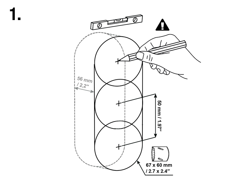
Cut a hole in the wall. The recommended hole depth is 56 mm.

Tip Download the drilling template from 2N.com.
-
Remove one of the blinds on the plastic box and pull the cables through. The recommended length of the accessible cables is 15 cm. Mind the two arrows engraved on the box bottom and the included blind to keep the proper installation orientation. Place the box into the wall hole. Use the four side bosses to determine the proper depth of the flush mounting. Use a walling material of your choice.
-
Use the four side bosses to determine the proper depth of the flush mounting. Make sure that the box edges are aligned with the wall after finishing the masonry. Break off the bosses after the walling material hardens.
-
Close the box with a blank. This prevents the walling and surfacing dirt from getting into the box surroundings.
-
Let the walling material harden after finishing the masonry and wall surfacing and remove the blank.
-
The package includes an L-shaped plastic plate and 3 Torx head screws. Cut 1–2 mm off the upper part of the cylinder-shaped rubber on the plate. Pull the cable through the remaining part. Use a crimping tool to crimp the cable connector and insert it in the terminal. Cover the terminal space with a plate and screw it.
Warning Keep the maximum tightening torque of 0.5 Nm.
-
Insert the metal device body in the walled-in box and fit it on the bottom using a Torx head screw.

Caution Loosen the screw if too tight to make the device fit in the box. Then tighten the screw again.
Can we advise you on anything else?
Take advantage of our technical support and sales specialists.